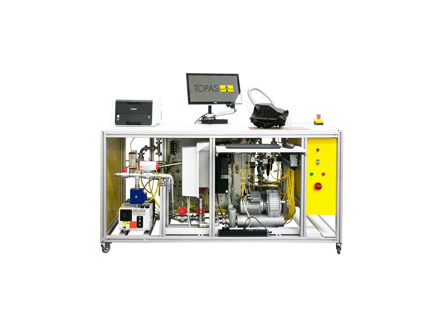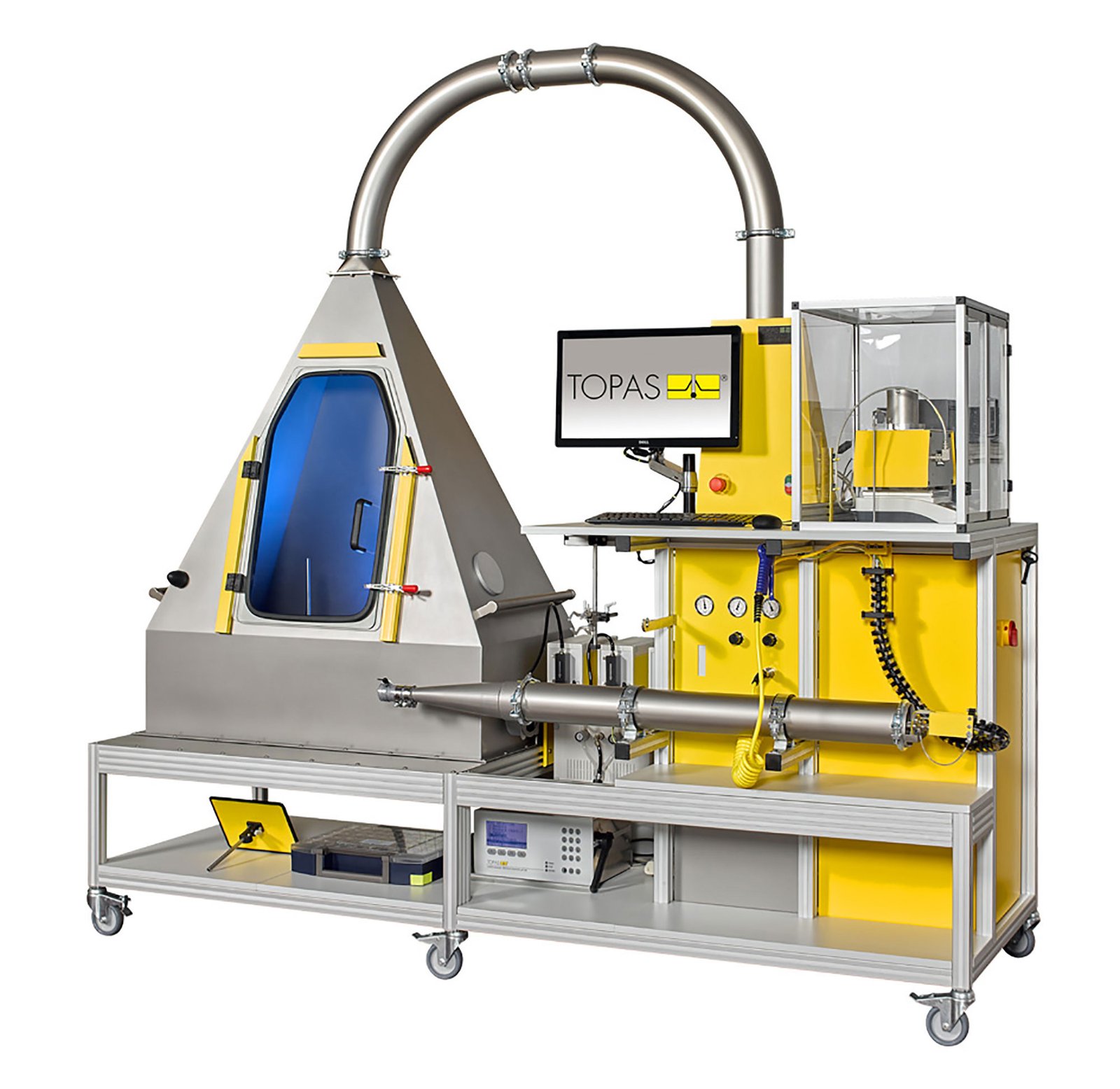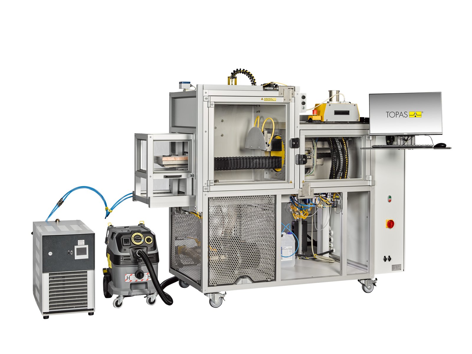
FST 144 Flow Scan Test System
Automated flow-scanning test system for characterising downstream air-velocity profiles and turbulence of filters, ducts and other flowed-through components across multiple airflow conditions.
Model Overview
| Model | System purpose | Standards / method | Core fit |
|---|---|---|---|
| FST 144 | Automated hot-wire scanning of downstream velocity fields and turbulence behind flowed-through components | Application-specific airflow methods | Flow-field characterisation, sensor-position optimisation and CFD-model validation |
Key Features
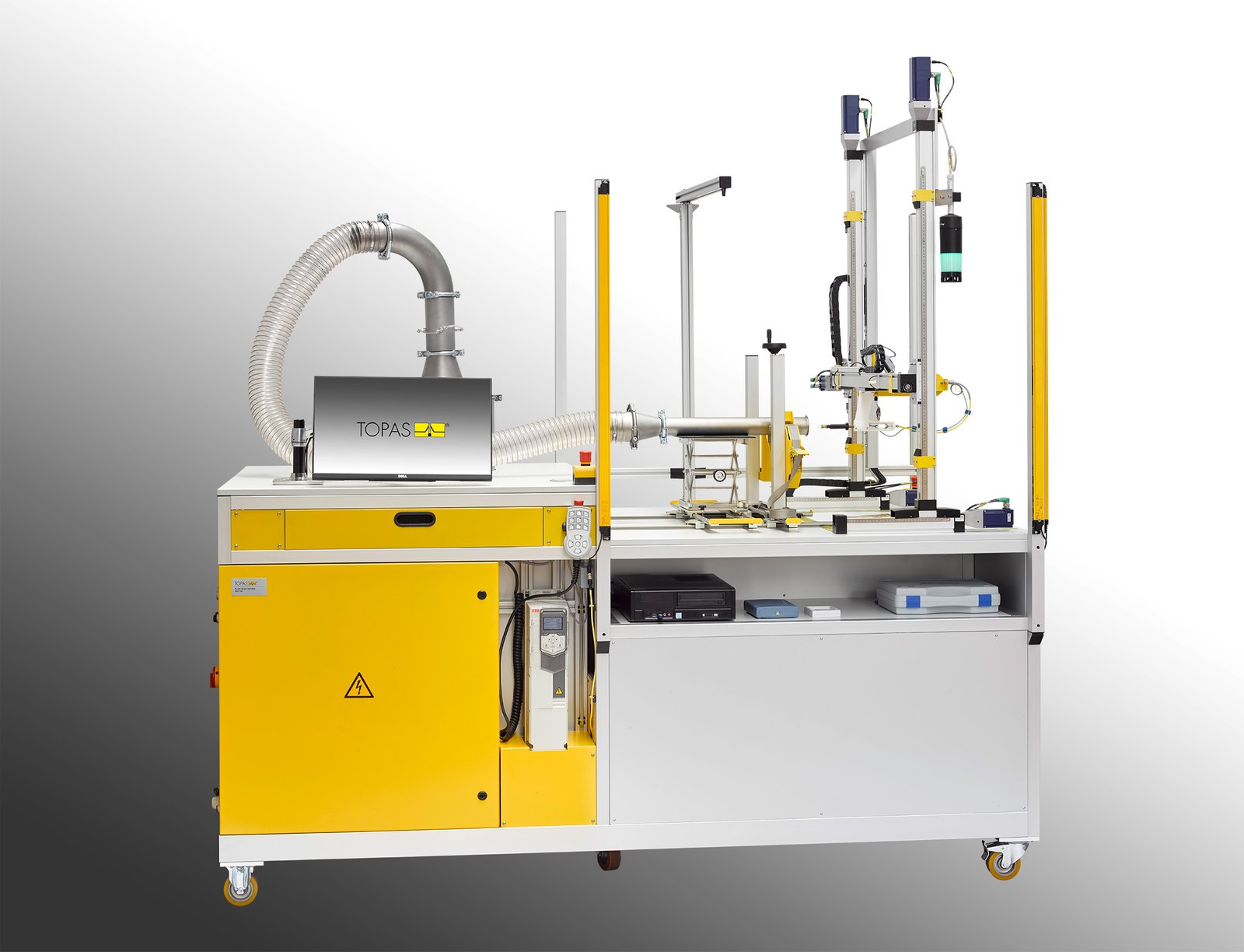
Automated planar scanning
A traversing system scans the downstream outlet plane with a hot-wire anemometer.
Velocity and turbulence analysis
Measures air velocities from 1 to 40 m/s and captures rapid fluctuations for turbulence assessment.
Wide airflow range
Supports test flows from 20 to 900 m³/h, with expansion up to approximately 1200 m³/h.
High pressure-drop capability
Accommodates significant pressure losses across specimens, connectors and hoses.
Graphical data evaluation
Fast data acquisition and visual presentation simplify interpretation of the measured flow field.
Simulation correlation
Measured velocity maps can be compared with CFD and other airflow-simulation models.
Technical Specifications
| Parameter | Unit | Value / Description |
|---|---|---|
| FLOW MEASUREMENT | ||
| Test-flow range | m³/h | 20–900; expandable to approximately 1200 |
| Air-velocity range | m/s | 1–40 |
| Measurement principle | — | Automated hot-wire anemometer scan downstream of the specimen |
| Maximum specimen size | mm | 485 × 600 |
| Pressure-drop capability | hPa | Up to 100 across specimen and periphery |
| SYSTEM DATA | ||
| Dimensions (W × H × D) | mm | 2500 × 2660 × 1300 |
| Weight | kg | Approx. 550 |
| Typical accessories | — | Hot-wire anemometer set and PC oscilloscope |
Published values support initial model selection. Confirm final configuration, utilities, accessories and calibration scope during technical review.
Applications
Velocity-profile mapping
Two-dimensional measurement of the outlet velocity field behind flowed-through components.
Air-duct development
Evaluation and optimisation of ducts, housings, tubes and connectors.
Filter-housing development
Characterisation of outlet-flow uniformity behind engine-intake and other filter assemblies.
MAF placement studies
Identification of suitable positions for mass-airflow and related velocity sensors.
CFD validation
Comparison of measured velocity fields with computational flow simulations.
Turbulence investigation
Fast acquisition of velocity fluctuations for component and airflow-system development.